Minimal Electrical Power System
A CircuitJS1 simulation of a CubeSat's power subsystem modeling battery charge/discharge cycles. The system includes a solar panel, a battery, and a load. The simulation demonstrates the power flow and management within the CubeSat's electrical power system.
Minimal EPS Circuit
The Problem As I Understood It
I understood the problem as the need to model a minimal Electrical Power Subsystem (EPS) for a CubeSat using CircuitJS1. The goal is to simulate the charge/discharge behavior over repeated sun and eclipse periods. The satellite is in the sun for 60 minutes (60 seconds simulation time) and in eclipse for 30 minutes (30 seconds simulation time). During the sun period, the system will receive approximately 6 W of solar power, which will charge the battery and power the loads. During the clipse period, the battery will be the sole power source for the satellite's loads. (Preview speed 100x & 30x respectively.)
UPDATED Circuit (With a pwl function.)
Use it here: https://tinyurl.com/2bvepyky
Circuit submitted on 5th September 2025 (Without a pwl function.)
Use it here: https://tinyurl.com/242qwz8d
Approach and Assumptions
My approach was to model each component of the Electrical Power Subsystem (EPS) individually, with all components drawing power from a central bus. For simulation simplicity, I assumed that 1 minute of orbit time is equivalent to 1 second of simulation time.
-
The Orbit: I designed the orbit as a current source controlled by a clock at required intervals. For the updated circuit, I used the pwl(t - 90*floor(t/90), 0, 0.811, 60, 0.811, 60.000000001, 0) fucntion to deliver 811mA of current at required intervels for a total of 90 seconds and staying ON for only 60 seconds, Generating 6W of power.
-
On Board Computer (OBC): The OBC is a continuous load. I connected it in parallel with the battery to ensure it remains powered throughout the entire orbit. It is represented as a resistor of 55 ohms.
-
Payload: This is a sun-only load. To model this, I placed it in series with the solar power source. This configuration ensures that it only draws power when the solar panels are generating electricity, as specified in the problem statement. It is represented as a purple LED in the circuit.
-
Battery: I understand the battery's role as power storage and delivery during an eclipse. I modeled it as a 7.4V voltage source in series with the main power bus, enabling it to be charged by the solar cell in the sun and to power all components (except the payload) during the eclipse. Since the software didn't have a specific battery component, I used two batteries in a "-++-" configuration to simulate a battery with charging and discharging behavior.
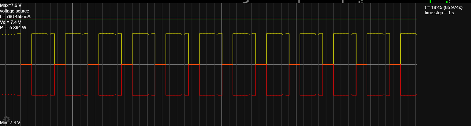
Plot: Intervals are 60 seconds (charging cycle, shown as yellow), 30 seconds (discharge cycle, shown as red) & Constant voltage of 7.4V (shown as green) & roughly 6W of power.
- TT&C and ADCS: As these loads are designed to operate in short bursts, I connected them in parallel with the battery and used a MOSFET controlled by a clock source. The TT&C has a brief duty cycle for its pulses, while the ADCS is activated with a larger delay to simulate less frequent operation. They are shown as resistors of 20 ohms and 15 ohms respectively in the circuit.
Tools and Resources
- Falstad’s CircuitJS1: https://www.falstad.com/circuit/
- Falstad’s CircuitJS1 Documentation: https://www.falstad.com/circuit/doc/
- Use: This documentation was referenced to understand the software's features, including how to set up timed sources and other circuit components.
- Gemini 2.5 Pro & Flash: https://gemini.google.com/
- Use: Gemini was used to help me understand terms like EPS, OBC, ADCS, and TT&C. It was also used for rechecking my math, fixing some errors, and helping solve some software limitations which are mentioned in the "Failures & Fixes" section.
Failures & Fixes
- Issue: Lack of knowledge regarding Timed Source (PWL) in CircuitJS1 * Problem: I failed to find the required built-in Piecewise Linear (PWL) or a ready-made timed source, which was required to simulate the sun and eclipse periods.
- Workaround: I used a Clock (CLK) with a specific waveform and a MOSFET. The clock is configured to produce a certain voltage to turn the MOSFET on and off.
- Issue: Ideal Current Source Limitations * Problem: The software had a limitation where ideal current sources had issues when used with MOSFETs and transistors, preventing proper operation by bypassing them regardless of gate voltage condition.
- Workaround: I added a manual switch to the circuit and synchronized its timing with the clock. This manual switch allows for the proper control of the MOSFET, effectively working around the software's limitation.
- Issue: No Battery Component * Problem: The CircuitJS1 software does not have a single, dedicated battery component that can model both charging and discharging behavior.
- Workaround: I simulated the battery's behavior by using two batteries in a "-++-" configuration, as explained in the Approach section. This setup allows for the proper representation of both charging from the solar source and discharging to power the loads.